|
|
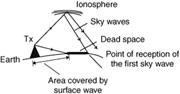
Skip Distance and Dead Space.
Skip Distance - is the distance between the transmitter and the point where the first sky wave return arrives. For a given frequency this distance varies with the time of the day.

Dead Space - is the area between the limit of the surface wave and the point of reception of the first sky wave. Dead space occurs mainly in the HF band. With increase in frequency, skip distance increases and surface wave range decreases. Dead space therefore increases with increases in frequency.
2). SATCOM (Satellite Communication System) - uses satellites as replay stations to transmit over long distances, instead of HF frequencies which are susceptible to atmospheric interference. SATCOM supports a wide range of services such as flight deck voice communications, passenger telephone/FAX and ACARS.
The satellite and ground station relay a wide range of data to and from the aircraft and airlines, airports, air traffic control and telecommunications via the public network. The satellite service, which is available to marine and land users as well as aviation, provides coverage by means of geostationary satellite between latitudes 80°N and 80°S. SATCOM will become increasingly important as ADS becomes effective. ADS is a system that uses satellite communication data links to allow air traffic control to monitor the position of aircraft by interrogating the on-board navigation systems such as GNSS.
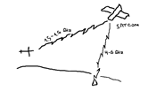
3). At what Frequency operate AWR.Commercial AWR systems operate in two frequency ranges in the SHF band:
· (G band) 4000 to 8000 MHz, example 5.44 GHz.
· (I band) 8000 to 12500 MHz, example 9.33GHz.
Билет №34
1). Ground Direction Finding. Ground stations with the facility of taking a bearing of an aircraft from that aircraft’s transmissions are shown in the relevant section of the AIP. Users are advised that bearing information will only be given when conditions are satisfactory; furthermore a number of facilities are shown as “not available for en-route navigations”. Worldwide such services may be provide in the MF and HF bands but in most countries it operates in the VHF and UHF bands only. As civil aircraft do not use UHF, effectively ground direction finding is limited to VHF.
2). Night Effect- revers to problems that occurs when sky waves are received from the tuned NDB. ADF is designed to use only the vertically polarized ground wave and communication by the sky wave will cause bearing errors and wandering of the ADF needle.
3). At what Frequency operate ADF. ADF equipment senses incoming radio waves as they arrive at the aircraft and measures their direction relative to the nose of the aircraft. The direction of the radio wave may be shown on a RBI or displayed on an indicator orientated with magnetic heading, known as a RMI. On the RMI, the ADF indication is the magnetic bearing TO the source of the radio waves. This bearing is referred to as the QDM. Frequency Bands – LF and MF. Frequencies- 190 kHz to 1750 kHz (most commonly 200-500kHz).
Билет №35
1.) VOR is an acronym for VHF Omnidirectional Range, also known as OMNI. Because it operates in the VHF band, it is not affected by many of the problems associated with ADF such static interference and night effect. It is similar to ADF in that is provides the bearing of the aircraft TO or FROM a transmitter at a known ground position. However whereas ADF equipment measures the direction of the radio wave when it arrives at the aircraft, the VOR airborne receiver decodes from the radio wave its direction when it left the ground transmitter.
2). Phase Difference - the phase difference is the angular difference between the corresponding points on the waveform and is measurable provided the two signals have a common frequency.
3). At what Frequency operate NDB - frequency surface wave range increases as frequency decreases because attenuation is reduced. 190 kHz to 1750 kHz (most commonly 200-500 kHz).
Билет №36
1). Radio Magnetic Indicator- the RMI is alternative indicator for VOR and ADF. For both VOR and ADF bearings, the orientation of the pointer is determined by relative bearing but the reading of the pointer when taken against the compass card is magnetic bearing to the aid (QDM). The compass card rotates to show magnetic heading against the index at the top. As the card must be driven, the RMI requires an electrical input of heading such as that provided by a gyro – magnetic compass.
2). Tracking by RMI - If the aircraft is on track between NDBs or VORs, the pointers on the RMI will be aligned. It can be readily seen from the RMI on which side of track the aircraft is located.
3). At what Frequency operate Ground Direction Finding - the frequencies to be used are in the AIP. An aircraft can call a VDF station and request true or magnetic bearings as follows:
• QTE – the aircraft’s true bearing from the station
• QUJ - the aircraft’s true track to the station
• QDR – the aircraft’s magnetic bearing from the station
• QDM - the aircraft’s magnetic track to the station
Билет №37
1). Instrument Landing System is a runway approach aid providing lateral and vertical guidance that allows aircraft to safely approach the runway from several miles out.
2). ILS Airborne Equipment - ILS equipment in the aircraft consists of a receiver with localizer, glideslope and marker beacon facilities, three aerials, a control unit, and an indicator displaying localizer and glideslope deviation and set of marker beacon lights. The control unit normally always either ILS or VOR frequency to be selected. Selection of the VHF localizer frequency automatically selects the paired UHF glideslope frequency.
3). At what Frequency operate Radio Telefone.Airband radiotelephones used for air to ground communication between pilots and controllers operates in the VHF band from 118.0 to 136.975 MHz, using amplitude modulation.
Билет №38
1). Marker Beacons - all marker beacons transmit on a radio frequency of 75 MHz. The energy pattern is fan shaped and mainly vertical with the result that there is very litter chance of interference. By comparing the pressure or radio altimeter readings with the published height of the glide slope at the markers, it is possible to check the proper functioning of the ILS. Passage over the markers also allows range from touch-down to be checked. Outer, middle and inner markers transmit on the same radio frequency but with different rates of amplitude modulation. The modulated signal contains Morse-type dots and dashes and activates the blue, amber or white lights which flash in synchronism with the dots and dashes.
2). Flag Alarms - will appear and the needles will centralize when:
· The aircraft is outside of the ILS service area.
· There is a significant fault in the transmission, e.g. modulation not deleted.
· The ground or airborne equipment is switched off.
3). At what Frequency operate MLS. The operating frequencies for MLS lie in a portion of the C-band (5030–5091 MHz) designated for use in aeronautical telecommunications. This frequency choice allows a 12-ft (3.6-m) antenna to generate the 1° beam width pattern needed to exclude most reflections.
Билет №39